
内容[ 显示 ]
在本教程中,您将学习如何控制高电流直流负载,例如直流电机或微控制器的白炽灯。微控制器只能从其输出引脚输出非常少量的电流。这些引脚用于发送控制信号,而不是用作电源。从微控制器控制另一个直流设备的最常用方法是使用晶体管。晶体管允许您控制来自低电流源的高电流电路的流量。
为了充分利用本实验,您应事先熟悉以下概念。如果您不是,请查看以下链接:
 |  |  |  |
|---|---|---|---|
| 无焊面包板 | 22-AWG连接线 | Arduino微控制器模块 | 10Kohm电位器 |
 |  |  | |
| 功率二极管(仅限直流电机版本) | DC power supply | TIP120 transistor | DC Motor |
| OR |  | ||
| Incandescent lamp and socket |
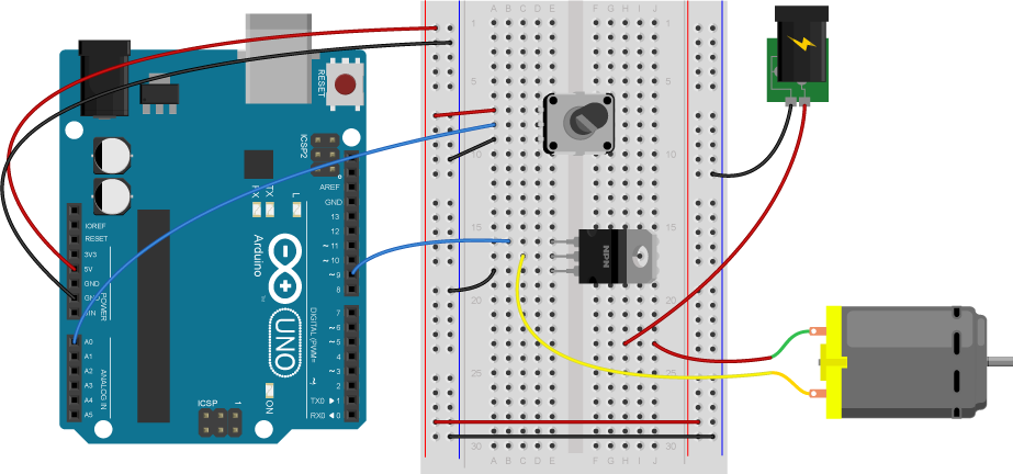
Connect the breadboard to the Arduino, running 5V and ground to the side rails:
Connect a potentiometer to analog in pin 0 of the module:
 |  |
|---|---|
| Schematic view | Arduino with Potentiometer |
The transistor allows you to control a circuit that’s carrying higher current and voltage from the microcontroller. It acts as an electronic switch. The one you’re using for this lab is an NPN-type transistor called a TIP120. The datasheet for it can be found here. It’s designed for switching high-current loads. It has three connections, the base, the collector, and the emitter. The base is connected to the microcontroller’s output. The high-current load (i.e. the motor or light) is attached to its power source, and then to the collector of the transistor. The emitter of the transistor is connected to ground.
 |  |
|---|---|
| Pinout of a TIP-120 transistor from left to right: base,collector, emitter | Schematic symbol of a TIP-120 transistor |
You can also use an IRF510 or IRF520 MOSFET transistor for this. They have the same pin configuration as the TIP120, and perform similarly. They can handle more amperage and voltage, but are more sensitive to static electricity damage. MOSFETs are grouped into N-Channel and P-Channel, which are equivalent to NPN and PNP bipolar transistors. Here’s a quick translation table for the pin names on both:
| Bipolar Transistor | MOSFET |
|---|---|
| Base | Gate |
| Collector | Drain |
| Emitter | Source |
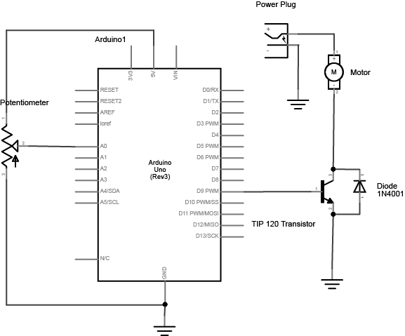
Connect the base to an output pin of the microcontroller, and the emitter to ground like so:
Safety Warning: You can generally connect the base to a microcontroller’s pin directly without a current limiting resistor because the current from the pin is low enough. But it’s necessary if you’re controlling a transistor circuit without a microcontroller.
Attach a DC motor to the collector of the transistor. Most motors will require more amperage than the microcontroller can supply, so you will need to add a separate power supply as well. If your motor runs on around 9V, you could use a 9V battery. A 5V motor might run on 4 AA batteries. a 12V battery may need a 12V wall wart, or a 12V battery. The ground of the motor power supply should connect to the ground of the microcontroller, on the breadboard.
Next, add a diode in parallel with the collector and emitter of the transistor, pointing away from ground. The diode to protects the transistor from back voltage generated when the motor shuts off, or if the motor is turned in the reverse direction.
 |  |
|---|---|
| The circuit with protection diode across the transistor | The TIP120 can be replaced with a MOSFET if you prefer. |
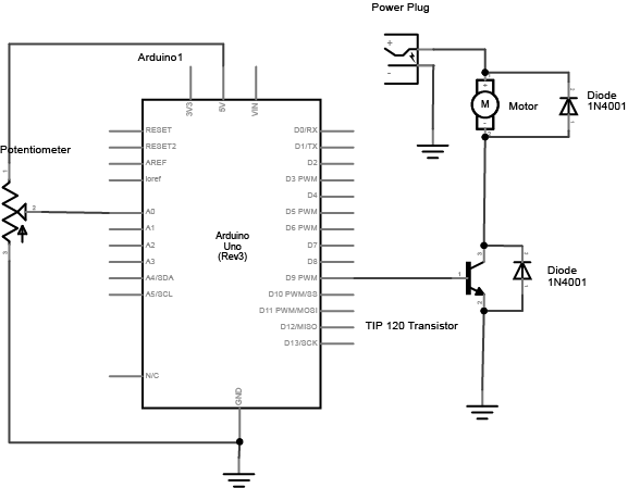
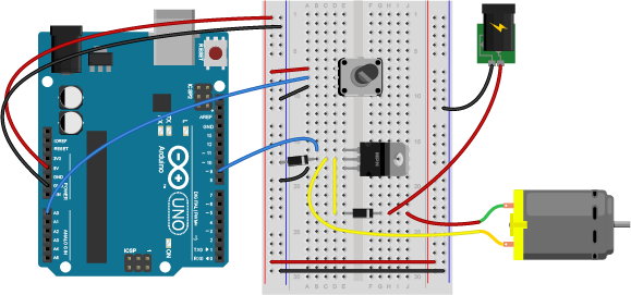
You may also find that adding a diode across the motor helps with back voltage protection as well, particularly when you’re running multiple transistor-motor circuits. If you plan to add a diode across the motor, here’s the circuit:
Be sure to add the diode to your circuit correctly. The silver band on the diode denotes the cathode which is the tip of the arrow in the schematic, like so:

This circuit assumes you’re using a 12V motor. If your motor requires a different voltage, make sure to use a power supply that’s appropriate. Connect the ground of the motor’s supply to the ground of your microcontroller circuit, though, or the circuit won’t work properly.
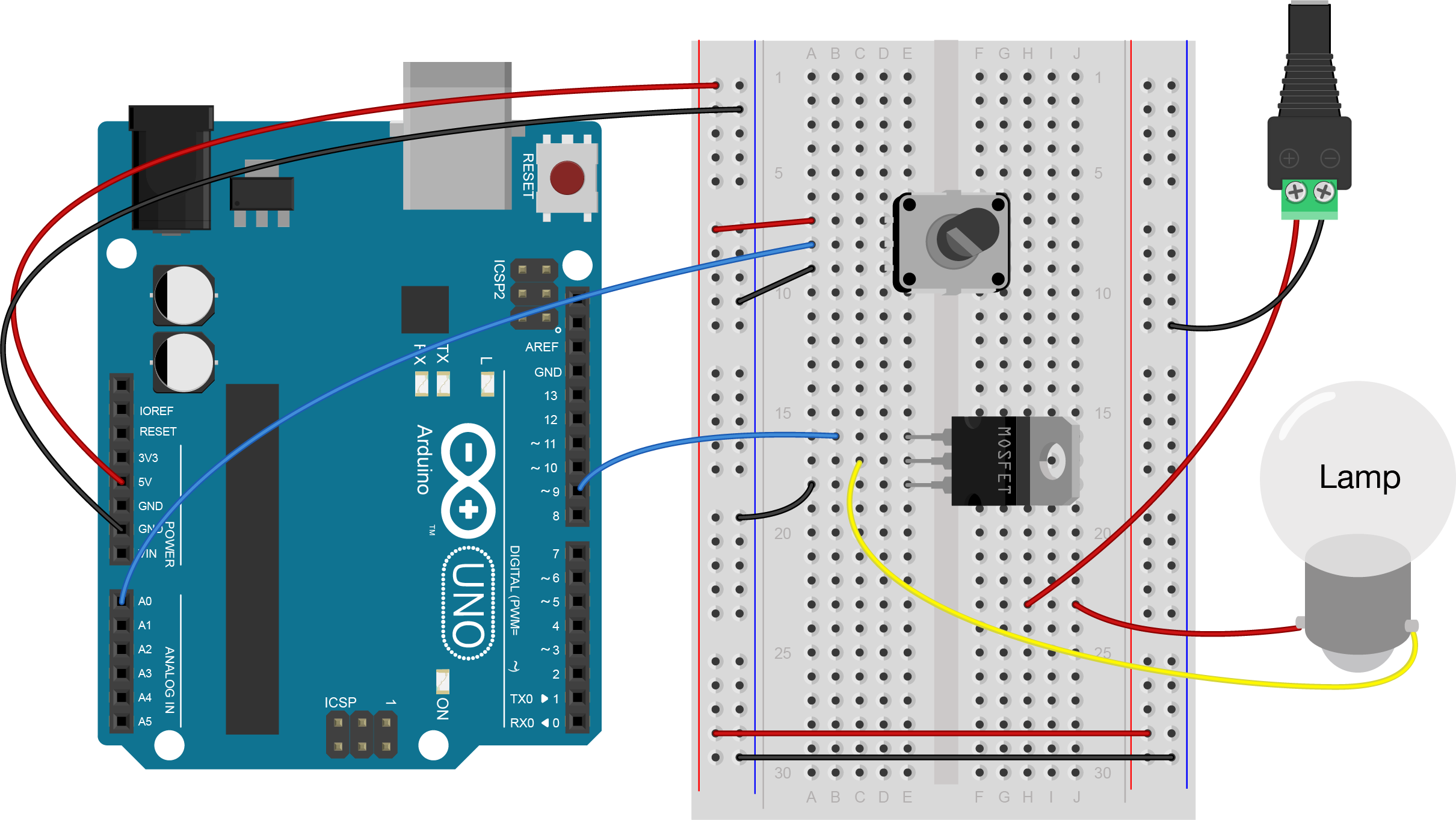
You could also attach a lamp using a transistor. Like the motor, the lamp circuit below assumes a 12V lamp. Change your power supply accordingly if you’re using a different lamp. In the lamp circuit, the protection diode is not needed, since there’s no way for the polarity to get reversed in this circuit:
Write a quick program to test the circuit. Your program should make the transistor pin an output in the setup method. Then in the loop, it should turn the motor on and off every second, just like the blink sketch does.
const int transistorPin = 9; // connected to the base of the transistor void setup() { // set the transistor pin as output: pinMode(transistorPin, OUTPUT); } void loop() { digitalWrite(transistorPin, HIGH); delay(1000); digitalWrite(transistorPin, LOW); delay(1000); } |
Now that you see it working, try changing the speed of the motor or the intensity of the lamp using the potentiometer.
为此,请使用电位计读取电压 analogRead()。然后将结果映射到0到255的范围,并将其保存在新变量中。使用该变量设置电机的速度或灯的亮度 analogWrite()。
const int transistorPin = 9; // connected to the base of the transistor void setup() { // set the transistor pin as output: pinMode(transistorPin, OUTPUT); } void loop() { // read the potentiometer: int sensorValue = analogRead(A0); // map the sensor value to a range from 0 - 255: int outputValue = map(sensorValue, 0, 1023, 0, 255); // use that to control the transistor: analogWrite(transistorPin, outputValue); } |
对于电机用户:这样控制的电机只能向一个方向转动。为了能够反转电动机的方向,需要H桥电路。有关控制带H桥的直流电机的更多信息,请参阅 直流电机控制实验室
联系客服


