Briefly explain the 8086 instruction format.
The 8086 instruction sizes vary fromone to six bytes. Depending on the type of coding, an instruction may have morethan one hex code.
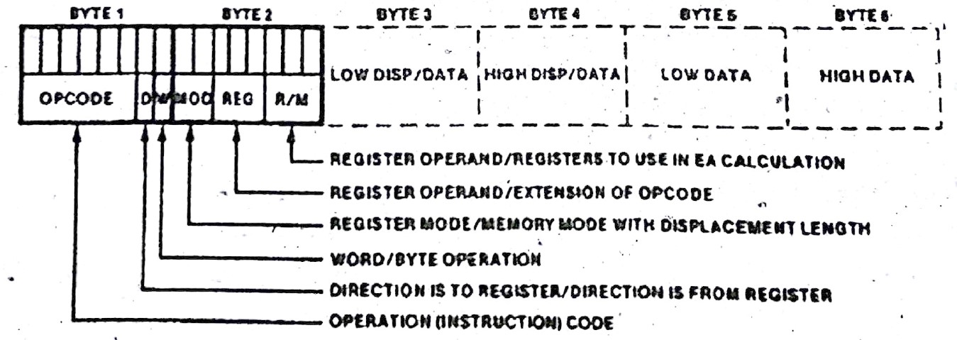
Figure below shows the instructionformat of 8086:
The first six bits of a multi byteinstruction generally contains an op-code that identifies the basic instructiontype i.e. ADD, XOR etc.
The following bit called the D fieldgenerally specifies the direction of the operation. D = 1 means instructionsource is specified in REG field. D = 0 means instruction destination isspecified in REG field.
The next following bit is W. This bitidentifies between byte and word operation. W = 0 instruction operates on bytedata. W = 1 instruction operates on word data. In some case in 2nd byte we haveMOD, OPCODE and R/ M and for some of the cases we have MOD, REG and R/M. First,OPCODE bits in 2nd byte of instruction format. This field is 3 bit wide. Underthat we have three single bit fields S, V and z.
(i)S bit: An 8 bit 2's complement number can be extended to a16 bit 2's complement number by letting all of the bits in high order byteequal the MSB in low order byte. This is referred to as sign extension.
S bit is used in conjunction with Wto indicate sign extension of immediate fields in arithmetic instructions.
S = 0 No sign extension
S = 1 Sign extended 8 bit immediatedata to 16 bits if W = 1
Therefore for 8 bit operation S = W =0
16-bit operation with a 16-bitimmediate operand S = 0, W = 1.
16 it operation with a sign extended8-bit immediate operand S = W = 1
(ii)V bit: Used by shift and rotate to determine single andvariable bit shifts and rotate.
V = 0 shift/rotate count is one
V = 1 shift/rotate count is specifiedin CL register
(iii)Z bit: This bit is used as a compare bit with zero flag inconditional repeat (REP) and loop instructions.
Z = 0 repeat/loop while zero flag isclear
Z = 1 repeat/loop while zero flag isset
MOD:The mode (MOD) field indicates whether one of the operands is in memory orwhether both operands are register.
Table below shows MOD field encodingthis field is of size 2 bits
| CODE | EXPLANATION |
| 0 0 | Memory mode, no displacement follows* |
| 0 1 | Memory mode, 8 bit displacement follows |
| 1 0 | Memory mode, 16 bit displacement follows |
| 1 1 | Register mode (No displacement) |
Except when R/M = 110, then 16 bitdisplacement follows. As seen MOD is basically concerned with displacement i.e.8-bit or 16-bit or no displacement.
REG:The register (REG) field identifies a register that is one of the instructionoperands. REG field depends upon W bit.
Table below shows the selection ofregisters depending upon W bit.
| REG | W = 0 | W = 1 |
| 0 0 0 | AL | AX |
| 0 0 1 | CL | CX |
| 0 1 0 | DL | DX |
| 0 1 1 | BL | BX |
| 1 0 0 | AH | SP |
| 1 0 0 | CH | BP |
| 1 0 1 | DH | SI |
| 1 1 1 | BH | DI |
When W = 0 ALL 8-bit registers areselected whereas for W = 1 all 16-bit registers are selected. Thus in a numberof instructions and mainly in immediate to memory variety, REG is used as anextension of the OPCODE to identify the type of operation i.e. 8-bit or 16-bit.
R/M:This field as of 3 bits. The meaning of R/ M bits changes depending upon mode(MOD) field.
CaseI: Register to register transfer: In this operation datamovement is within the register either 8 bit or 16 bit. As mentioned in thisoperation, REG field identifies one of the instruction operands. The otherinstruction operand is specified by R/M, W and MOD bits. R/M field encodingwhen MOD = 11 (binary)
| REG | W = 0 | W = 1 |
| 0 0 0 | AL | AX |
| 0 0 1 | CL | CX |
| 0 1 0 | DL | DX |
| 0 1 1 | BL | BX |
| 1 0 0 | AH | SP |
| 1 0 0 | CH | BP |
| 1 0 1 | DH | SI |
| 1 1 1 | BH | DI |
CaseII: Memory mode (8 bit/ 16 bit or no displacement):When MOD selected memory mode (MOD = 00 or 01 or 10) then data transfer isregister to/from memory. In that case R/ M field indicates how the effectiveaddress of the memory operand is to be calculated.
本站仅提供存储服务,所有内容均由用户发布,如发现有害或侵权内容,请
点击举报。